For me, the first stage of creating any new product is identifying and thoroughly understanding the core problem it aims to solve. If a mature solution already exists on the market and fully satisfies user needs, there is no point in manufacturing a product that brings nothing new to the table or fails to improve the operational experience for real-world end-users.
It is equally critical to understand the future application of the product and its target user. In this regard, we must recognize that solutions designed for competitive sports are rarely ideal for military deployment—and often, vice-versa.
When the time came to design our new red dot mount line (RDM), one of the first challenges we identified was the lack of cross-brand compatibility between red dot sights and magnifiers in standard, factory-issued mounting systems.
The Problem of Cross-Brand Compatibility
Why is this issue so critical today? In the conditions of full-scale warfare, military personnel rarely have the luxury of time to read reviews, compare gear specs, or order tailored accessories. While it is unfortunate that they frequently purchase equipment out of their own pockets, they must also work with whatever is provided by the state, supplied by volunteers, or acquired as battlefield trophies. Consequently, their optical setups are almost never from a single manufacturer.
Different manufacturers enforce their own internal standards for optical centerline height. It is fortunate if they specify these measurements in their technical documentation, but many simply label products as "Absolute Co-witness" or "1/3 Lower Co-witness." If you collect a dozen different red dot sights and magnifiers from various brands and physically measure the distance from the Picatinny rail to the center of the optical axis, you are practically guaranteed to find variances of several millimeters.
When utilizing a standalone red dot sight, this issue is manageable. Replacing a factory mount with an aftermarket solution is straightforward, given the abundance of dedicated risers for specific footprints (Micro, MRO, ACOG) or universal Picatinny risers. However, the moment you introduce a magnifier behind the red dot, the first major issue arises: optical centerline misalignment.
Misalignment and Optical Distortion
In theory, this minor misalignment can be mitigated because most modern magnifiers feature internal windage and elevation adjustments to center the reticle within the field of view. However, we strongly recommend zeroing your primary red dot sight without the magnifier engaged and testing it afterward, as potential optical distortion is inevitable and can introduce significant aiming errors during firing.
Furthermore, based on extensive consultations with users—particularly operators over the age of 40 whose eyesight is no longer perfect—many report significant optical distortion. Under misalignment conditions, a crisp red dot can blur into a line, an arc, or a slanted figure-eight.
Some notice this distortion during observation, while others connect it with the perceived instability of the magnifier mount during rapid firing. While adjusting the physical alignment and experimenting with the distance between the sight and the magnifier can sometimes eliminate these distortions entirely, it remains a systemic flaw in standard setups.
The Shift Toward Modular Systems
Around 2023, we observed a profound shift in the dynamics of modern warfare. Beyond the obvious rise of unmanned systems, the doctrine surrounding small arms employment changed drastically. The integration of thermal imaging devices into primary optics setups became widespread, shifting tactical scenarios rapidly. We began receiving a high volume of requests for a fundamentally new mounting ecosystem—one that would allow operators to rapidly and reliably reconfigure their optical systems to match changing battlefield threats "here and now."
This demand clearly defined our second engineering challenge: Modularity.
In our engineering philosophy, modularity means the ability to quickly, securely, and seamlessly attach auxiliary modules—such as magnifiers, thermal clip-ons, laser aiming devices (LAMs), or secondary backup sights—to the primary optics system without sacrificing zero (POI retention) or performance.
A modern thermal device is no longer just a clip-on attachment. Today’s systems allow operators to activate a digital reticle and use the device as a primary sight, or mount it directly onto a helmet for observation alongside night vision goggles (NVG). Essentially, a thermal unit must now be capable of operating in front of the day optic, in place of the day optic, or completely detached on a helmet.
Operational Scenario Analysis: The Three-Device Cascade
Let’s analyze a common multi-optic operational scenario:
- Daytime Operations: The rifle is equipped solely with the primary red dot sight. This setup minimizes front-end weight and reduces operator fatigue during extended transitions.
- Extended Range Engagement: If the operator needs to positive-identify a target or execute a precision shot at distance, a magnifier can be engaged or mounted instantly.
- Thermal Identification: In dense or wooded terrain, identifying target signatures requires thermal imaging. The operator can use the thermal device as a handheld monocular or mount it to a helmet (personally, I prefer the handheld monocular method for ergonomics).
- Target Engagement: Once a target is identified and the decision to engage is made, the thermal device is mounted directly onto the weapon.
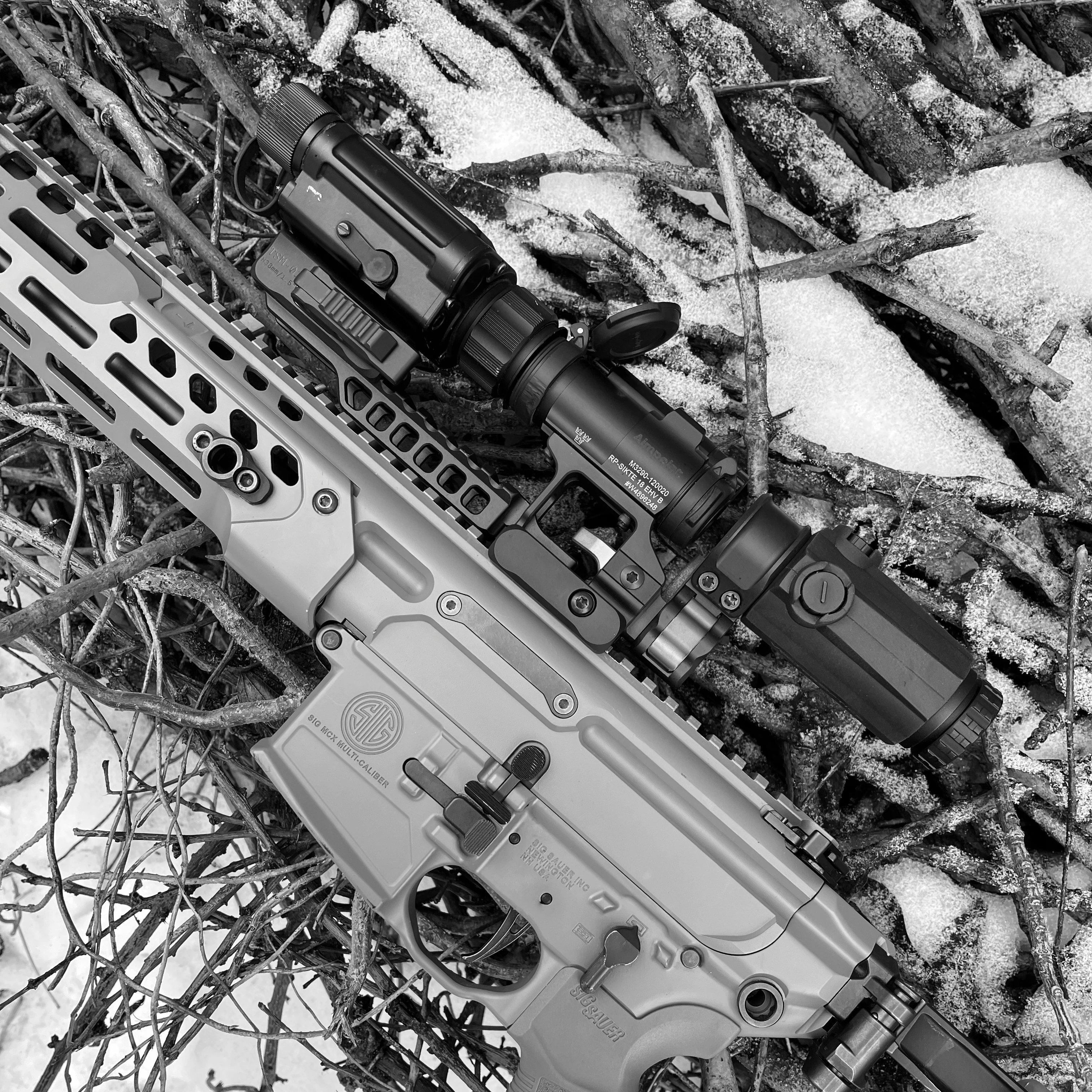
In this specific configuration, you end up running three devices inline: the thermal unit, the red dot sight, and the magnifier. Why? Because a thermal device is an electronic system, not a traditional glass optic; it is essentially a micro-display. The red dot from your primary sight projects onto this display to mark the point of impact. Because this display sits relatively far from the eye, the magnifier is required to bring the digital image (along with the red dot) closer to the shooter’s eye.
This brings us right back to the critical issue of optical centerline alignment. In a three-device cascade, even a slight misalignment transitions from a minor annoyance to a critical failure. Misalignment severely restricts your field of view because your image sits inside a limited "window" of the thermal screen, which you are viewing through the housing of a red dot sight, followed by a magnifier. Furthermore, structural rigidity and stability (the elimination of play during observation and recoil) are paramount; any mechanical instability induces severe optical distortion.
Redundancy and Repeatability
According to the scenario above, if your kit includes a thermal device capable of acting as a standalone primary sight, your mounting system must accommodate this capability. In the event of a red dot failure or a transition to complete darkness requiring a dedicated thermal weapon sight, the mounting hardware must feature a Quick-Detach (QD) mechanism with absolute return-to-zero repeatability.
An operator must be able to strip the red dot sight off the receiver, mount the thermal device in its place, activate the digital reticle, and immediately engage targets without needing to re-zero the weapon. This is the logical standard modern equipment must meet.
An Ergonomic Note on Handheld Monoculars: Why do I personally prefer using a thermal device as a handheld monocular over helmet-mounting? As mentioned, a thermal unit is an electronic display rendering a digital feed from a sensor, meaning it introduces native frame-rate latency. When running a thermal unit over one eye—or inline with an NVG—your vestibular system registers rapid head movements, but your eye perceives a delayed feed. After 10 to 15 minutes of continuous movement under these conditions, spatial disorientation and motion sickness inevitably set in.
Down-To-Earth Engineering: Ergonomics, Weight, and Rigidity
While alignment and modularity represent the strategic directions of our RDM product development, dropping down a level brings us to highly specific engineering constraints: ergonomics, weight distribution, and structural rigidity.
1. Right-Side Ergonomics
Unlike precision optics mounts designed for bolt-action rifles—where all protruding elements, such as QD levers, sit on the left side to clear the bolt throw—mounts for the AR-15 platform require the opposite approach. Protruding hardware should be oriented on the right side.
The right side of an AR-15 upper receiver already contains the forward assist and ejection port cover. The left side, conversely, is typically pressed flat against an operator's body or plate carrier during transitions and dynamic movements. Left-side levers constantly snag on tactical gear.
Furthermore, on weapon systems featuring left-side charging handles—such as the CZ Bren 2 or FN SCAR—left-side mounting hardware poses a severe risk of scraping or trapping the operator's knuckles during manual cycling. Having experienced this issue firsthand on a CZ Bren 2, I mandated that all protruding components on the RDM line reside strictly on the right side.
2. The Weight vs. Rigidity Fallacy
Weight is undeniably critical; every extra gram carried on the weapon translates exponentially into muscular fatigue over hours of operation. However, chasing extreme weight reduction on every component can lead to an engineering dead end.
Every aluminum alloy, even premium aerospace grades like 7075-T6, has a finite yield strength. Manufacturing high-end components requires managing a constant trade-off between mass and structural rigidity. Stripping too much material sacrifices rigidity, directly compromising reliability and zero retention under hard use. For military applications, structural integrity and rugged dependability must always take priority over shedding a few fractions of an ounce.
3. Integrated Secondary Sight Channels
We also integrated compatibility with mechanical backup iron sights (BUIS). Where geometry permitted on specific RDM models, we engineered an open visibility channel featuring integrated reference notches. This allows the operator to utilize the front sight post in tandem with the mount's rear notch as an emergency backup aiming system.
While it won't deliver match-grade precision, for emergency engagements at silhouette targets within 50 to 100 meters, it is far better than nothing. That said, we must remain realistic: if your vision is compromised, or you are operating under extreme stress, effectively tracking iron sights—or any mechanical backup—is incredibly difficult without hundreds of hours of dedicated muscle memory and continuous training. Recognizing your limitations is a form of operational strength.
Conclusion
The DAVIKA RDM Line and the ecosystem built around it were engineered from the ground up to solve these exact systemic challenges. It provides perfect optical centerline alignment across mismatched brands, introduces true modular flexibility for multi-device cascades on the fly, prioritizes snag-free right-side ergonomics, and strikes the perfect balance between lightweight design and uncompromising structural rigidity.


